Initial setup of a device with SSG's MIRTOS Operating System
We need some way to communicate with the microcontroller. Although it is possible to do so without a USB port, that is an advanced topic.
The initial hardware setup depends on which device you're using. If
your device already has a USB port attached to the first (or only)
Let's start with an Arduino ® Pro Mini which has had its bootloader replaced with MIRTOS. The first thing needed is to attach some header pins for the USB breakout board. Although soldering is beyond the scope of MIRTOS, Photo 1 below shows a circuit board in its original (bare) condition and three boards (3) with headers to its right.
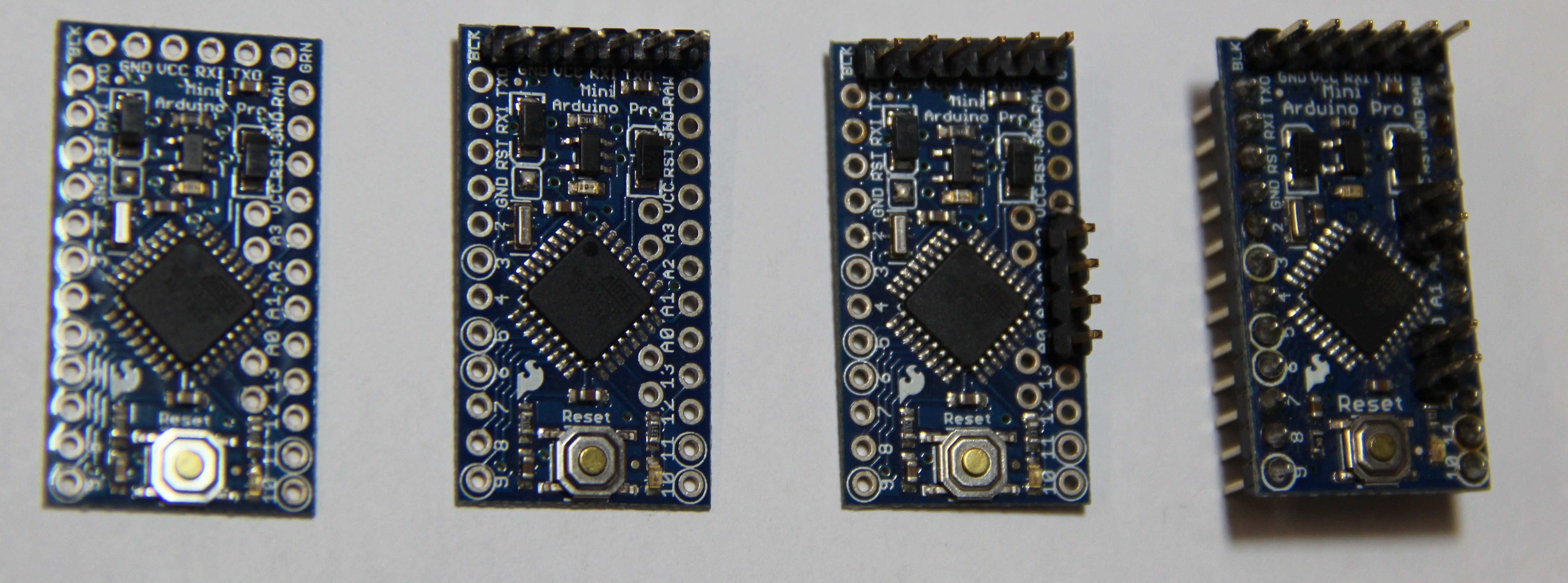
Photo 1.
The second board above only has header pins added to its six (6) plated through holes at the top of the board in Photo 1. These are to connect to its serial port, and they are soldered upward. To be clear, the soldering is done on the side not shown, but with the longer pins to which the connection is made extend upward, so the FTDI interface board connects above the circuit board. This header only provides the external connection for the serial port, leaving all the other pins available for additional connections later. There are very few, if any, reasons to solder the serial port header with pins pointed downward.
The next one to its right has those plus the four (4) pins identified as A0, A1, A2, and A3 with header pins, again all soldered with pins extending upward. A0 through A3 are connected to the input/output PORT C on the 328P microcontroller. This version is useful for testing, or if only a few I/O are needed. If this circuit board is to be inserted into a breadboard, this is probably NOT the best configuration.
Finally, the rightmost board in Photo 1 has all twelve (12) pins along each long edge soldered downward and the six (6) serial port pins as well as the four (4) not on the edges soldered upward. Those last four (4) are only labeled on the opposite side of the board as A4, A5, A6, and A7. A4 and A5 are connected to PINs C4 and C5, while A6 and A7 are connected to ADC6 and ADC7 of the 328P microcontroller. This version is best when planning to use a breadboard or protoboard to connect additional components.
The simplest connection is to attach an FTDI breakout board directly to the serial port header pins, as show in Photo 2. It provides both communication and power to the 328P board. Under the default MIRTOS configuration, the green onboard LED will blink as a heartbeat indicator, changing state once each second. Just connect a USB cable between the USB connector and your computer to complete the hardware communication link.
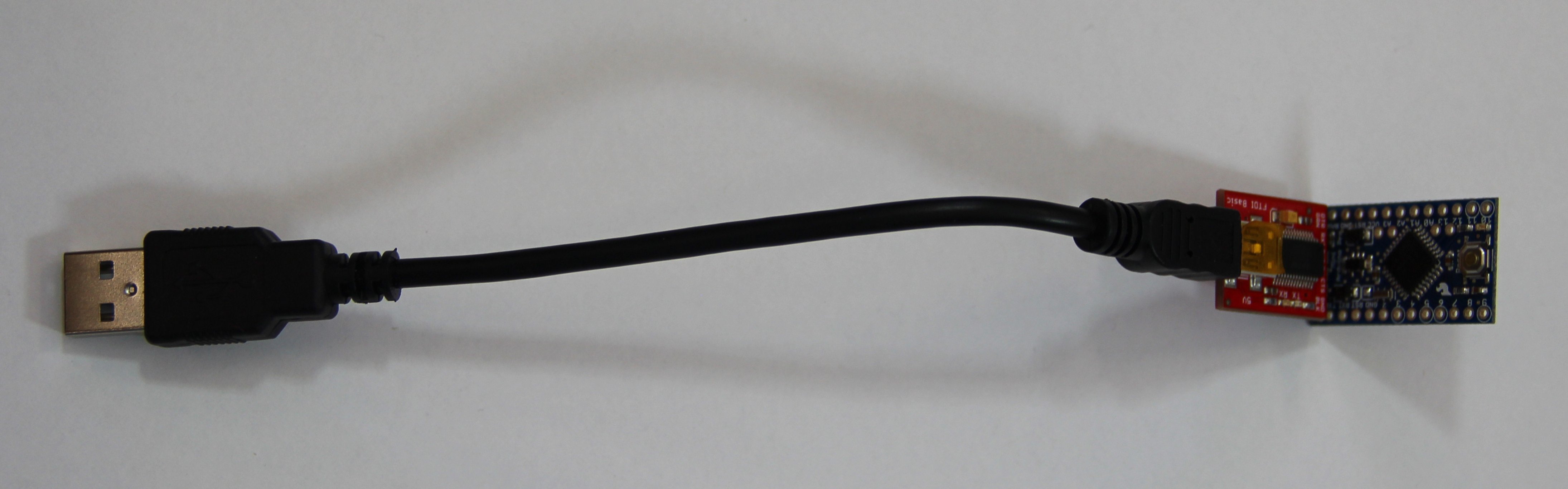
Photo 2.
If you plan to use a breadboard, you may also find it easier to complete the breadboard wiring before inserting a 24-pin circuit board into it. Certainly, if there are a lot of connections and some need need be run under the 328P board, it will be much more convenient to make all the wiring connections first. Removing a 24-pin board from a breadboard can be tough on both the individual doing it and the header pins.
In Photo 3 below, the rightmost board above has been inserted into a breadboard after it was wired. Notice that the serial port pins have been brought out to another 6-pin connector on the breadboard, but with one of the pins was skipped. This was done both to prevent the circuit board from being auto-reset every time the USB terminal session is started and stopped and for demonstration visibility. Since there are no bootloader and no "sketches" to be downloaded, the auto-reset is more of a bug (perhaps "annoyance" would be a more friendly term) than a feature for boards with MIRTOS.
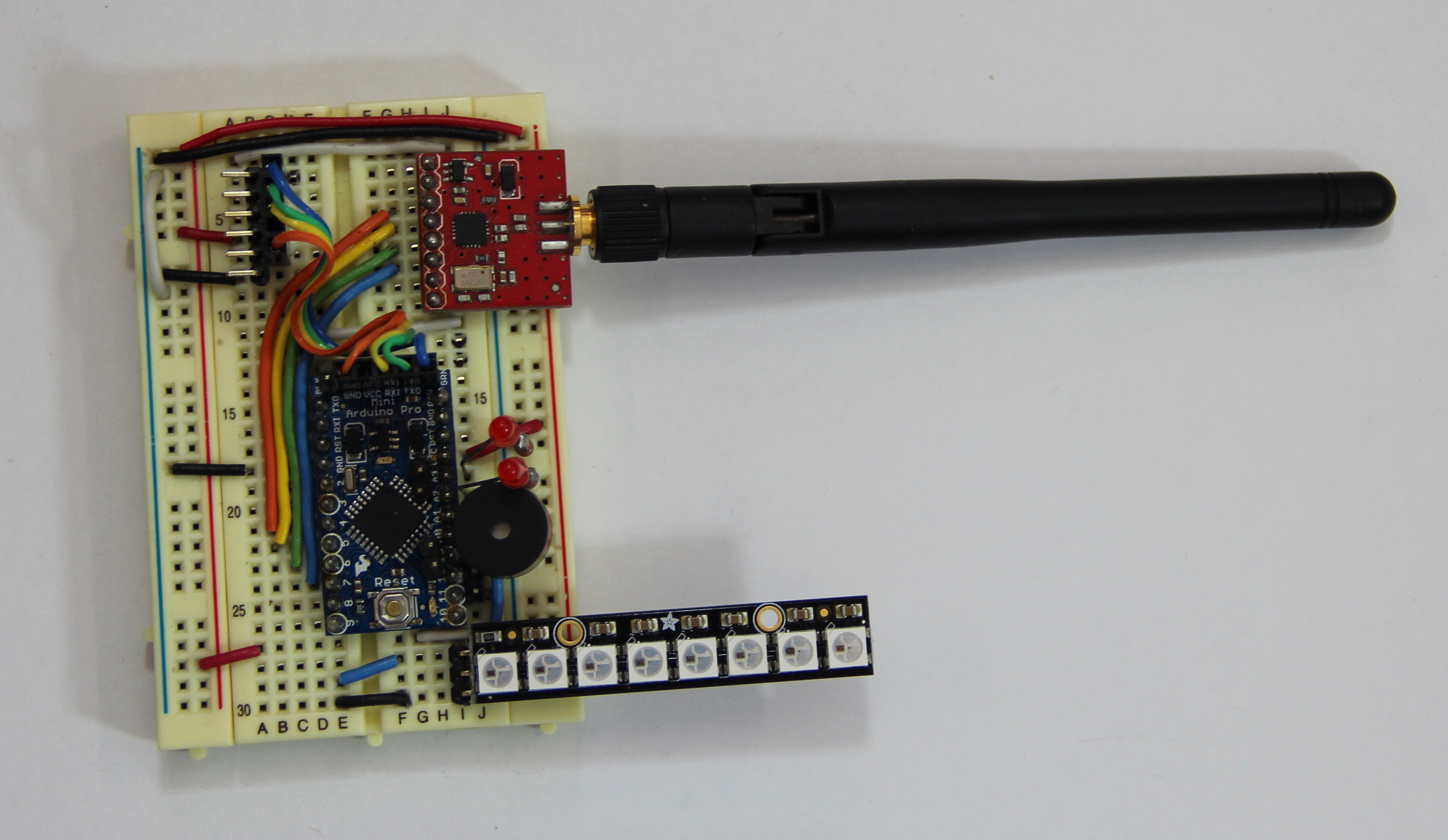
Photo 3.
The unit shown above also has a strip of eight (8) WS-2812
In any case, the next step is to start a serial port terminal program
on your computer as the Command Line Interface (CLI) into the the device.
When using the